E4S
Your First Circuit and Program
Material for a UC Irvine course offered by the Department of Physics Astronomy and developed by David Kirkby.
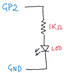
Build the circuit below using a Pico W microcontroller (not yet connected to your laptop via USB), a 1KΩ resistor, a red or green LED (your choice), your breadboard and some jumper wires:

Note that an LED is directional, i.e. does not work the same way forwards and backwards. This means you need to insert it into your breadboard with the correct orientation. Don’t worry if you get this wrong since it will not do any damage. In this case, the longer wire on the LED should be connected to the resistor (through a hidden breadboard wire).
The corresponding electrical circuit diagram is:
Why the resistor? A diode is not a linear component that obeys \(V = iR\). Instead, it has a non-linear voltage versus current curve. In this circuit, the diode operates in its forward-biased mode, so effectively has a fixed voltage drop of \(\Delta V =\) 2-3 V. The remaining voltage drop across the resistor \(V_{3.3} - \Delta V\) determines the current \(i\) flowing through both the resistor and diode, \(i = (V_{3.3} - \Delta V)/R\), which is proportional to the resulting light intensity. Therefore a forward-biased diode always requires a sufficiently large series resistance \(R\) to avoid exceeding the power supply’s maximum available current.
The light-green microcontroller pins labeled GP2, GP3, GP4, … are for general-purpose digital input and output. In this context, digital means that signals are represented by a voltage that is either close to 0V (“low”) or close to 3.3V (“high”). To complete your circuit, connect the Pico W to your laptop with a USB cable. This will apply power to your circuit (from your laptop’s USB port) and start running any previously loaded program, but there probably won’t be any sign of this.
To bring this circuit to life, enter the following program into your editor:
import board
import digitalio
import time

led = digitalio.DigitalInOut(board.GP2)
led.direction = digitalio.Direction.OUTPUT

while True:
    led.value = not led.value # toggle on/off
    time.sleep(0.5) # seconds
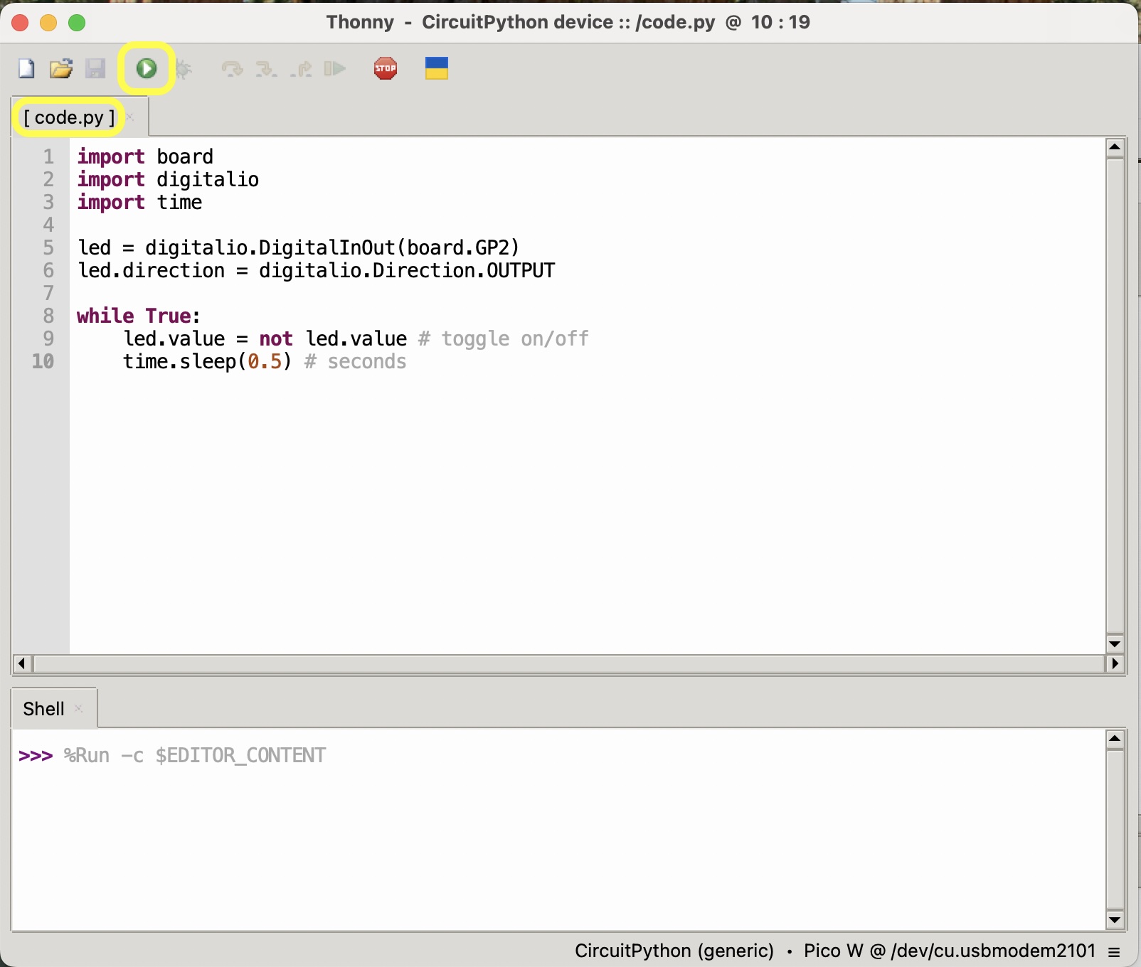
To test this program, click the green Run arrow in the Thonny toolbar (circled in yellow below). This triggers the Mu editor to download your program via the USB cable and reset the processor so that it starts running your code. If all goes well, you should now see your LED blinking once per second, alternating 0.5s ON then 0.5s OFF.
It is important that your program is saved to the top level of your CIRCUITPY drive (so not under the lib folder, for example) with the name code.py since this is what CircuitPython expects. Check the name in the editor tab, circled in yellow below:
In case your program is saved with a different name, it will not be running. To fix this, use File > Save As… to open a dialog where you can re-save it as
code.py
If you already have experience with python programming, you might notice a few new features in the MicroPython world. First, the imported board and digitalio modules are specific to your Pico W microcontroller board. Second, the digitalio module allows you to control a (digital) voltage in your circuit as if it were a normal python variable, with True corresponding to the “high” (3.3V) logic level and False corresponding to “low” (0V). You will soon learn how to control an analog voltage (with values anywhere between 0 and 3.3V) and measure both digital and analog voltages in your circuit.
What happens if you make a mistake writing your program? Remove the “a” from “import board” on the first line and run your code to see what happens:
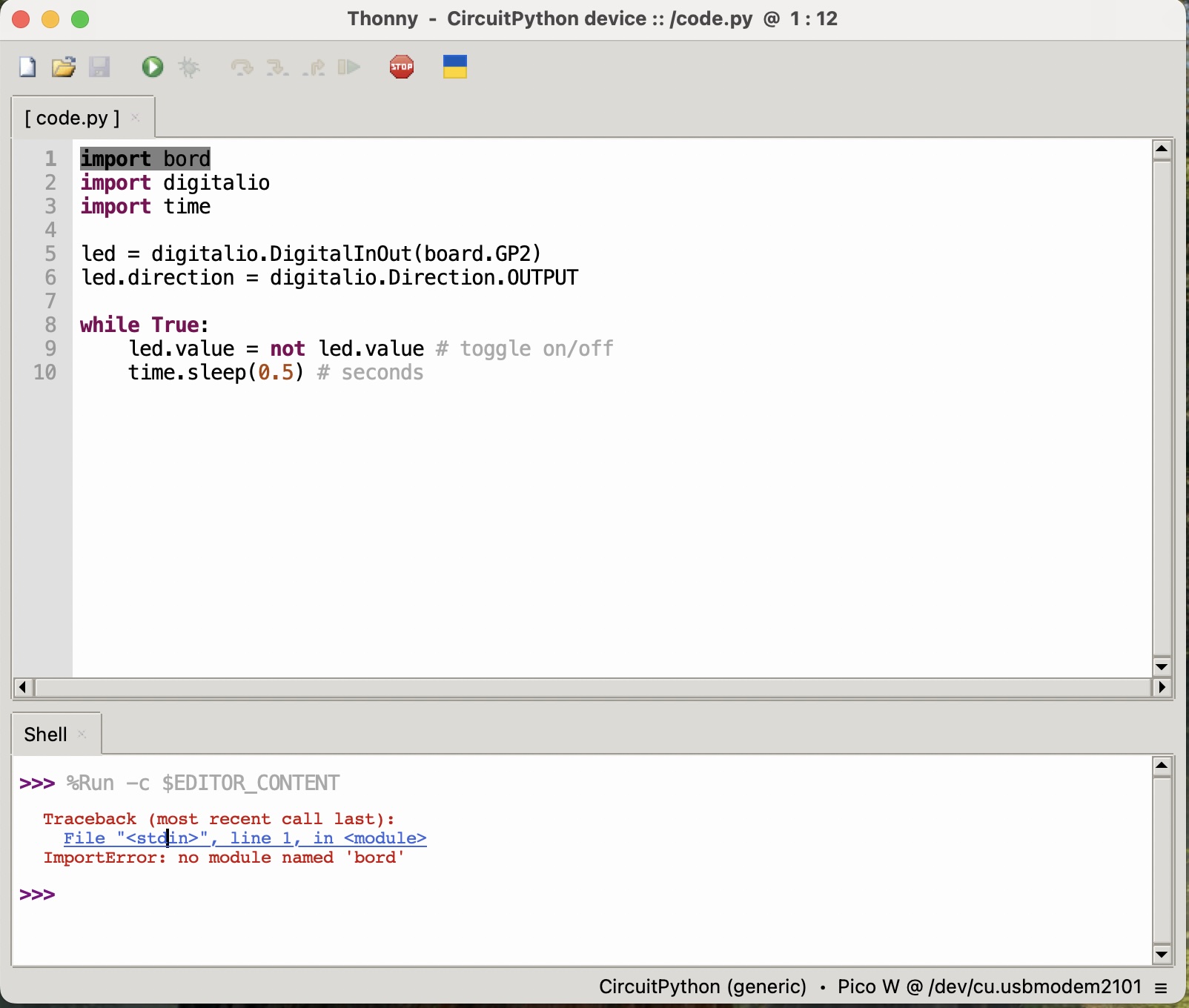
Note the error message printed in the lower “Shell” window. Links in this error message will highlight the specific line that triggered the error. Now fix this error and re-run.
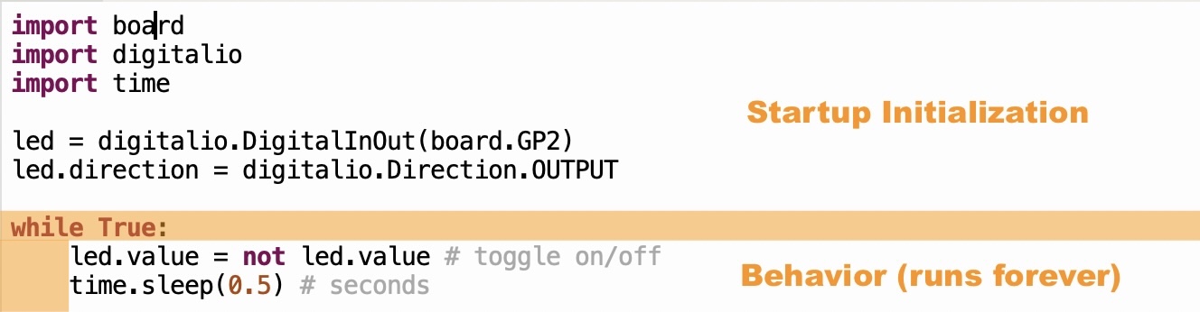
Running a program on the Pico is quite different from running a program on your laptop where, after turning it on (or rebooting it), you can select and run multiple programs then quit them when you are done. Life on the Pico is much simpler: it only runs one program that starts immediately when it is turned on (or rebooted), and runs that program forever (until you turn it off or reboot). Pico programs generally all have the same simple structure:
- lines before
while True:execute once, when the program starts, so are used for initialization - lines after
while True:are indented, and execute repeatedly forever, so determine the program’s behavior
Here are some experiments to try with your circuit and code. For each one, predict what might happen, try it then, in case you are surprised, think about why. The circuit changes below can be safely performed while your Pico is powered via USB.
- Turn the LED around
- Remove the resistor
- Replace the 1KΩ resistor with a 10KΩ resistor (and review Why the resistor? above)
- Change the 0.5 second delay to something much smaller or bigger
- Use a different GND pin on the Pico W
- Use a different GPn pin on the Pico W (can you modify your code to make this work?)
- Unmount the CIRCUITPY USB drive from your laptop and plug it into a USB charger